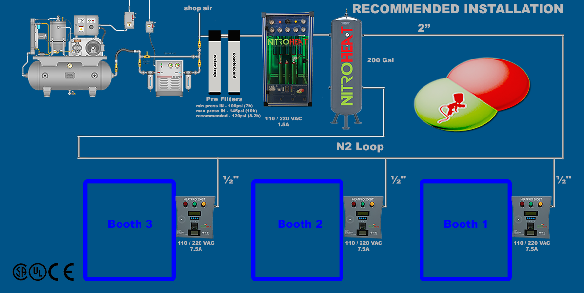
Installation


INSTALLATION NOTES
- USE BALL VALVES IN THE FOLLOWING LOCATIONS:
- Before the pre filters
- After the generator
- After the receiver tank
- Before each Heater (HP200)
- PIPING:
- Aluminum piping is recommended
- Always create a loop from and to the receiver tank
- Use 45 degree angles instead of 90 degree angles where possible
SYSTEM REQUIREMENTS
| NM15 | NM15 | NM30 | NM30 | NM30 | |
| No of Spray Booths | 1 | 2 | 2 | 3 | 4 |
| No of Painters | 1 | 1 | 2 | 2+ | 2+ |
| HeatPro 200 + 50 ft Heated Hose | 1 | 2* | 2 | 3* | 4* |
| Min Air Volume cfm/lpm | 20 / 566 | 20 / 566 | 40 / 1132 | 40 / 1132 | 40 / 1132 |
| Min Air Pressure psi/bar | 100 / 7 | 100 / 7 | 100 / 7 | 100 / 7 | 100 / 7 |
| Min Receiver Tank Gal/Litres | Optional | Optional | Optional | 100 / 350 | 130 / 500 |
NM15 includes 1 x HeatPro 200
NM30 includes 2 x Heatpro 200
*Additional Heatpro 200/s required
- N2 GENERATOR
- Install the generator in the paint shop as close to the pre-filters as possible. The generator can be either wall or floor mounted.
- The generator will operate on both 110/220VAC
- The current draw of the generator is 2A
- HP200 (Heater Controller)
- 1 x HP 200 is required for each spray booth or prep station
- Mount upright OUTSIDE spray booth.
- The HP 200 will operate on both 110 / 220VAC
- The current draw of each HP200 is 7A
- Connect regulator to the input of heater controller
- Connect heated hose, thermocouple connector and heater power cables to the top of the heater
- Route heated hose through spray booth wall and add quick connect to attach to spray gun/s
- Connect N2 line to the regulator
- Connect power
- Switch ON
- Check Green LED, Temp controller and multimeter turns ON.
- Set temperature
- Allow air / N2 to flow through the system and monitor temperature increase when air flows through hose
- Switch off at night
Hose Thermocouple Connector:
Thermocouple plug fits in ONE way only. Make sure the polarity is correct
Test to ensure that temperature rises when air flows through the heater. (if temperature decrease during air flow, the thermocouple connector is reversed.)
- NHH50 (heated Hose)
- The heated hose must be connected to the HP 200
- The heated hose must not be disassembled under any circumstances
- DO NOT DRIVE OVER THE HEATED HOSE

